Back to Top
Joystick Potentiometer JH-D202X-R2 5K
DESCRIPTION
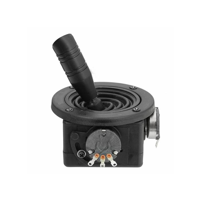
This large panel mounted Joystick provides a nice finished look as well as finer 2-Axis control than is possible with a standard thumb joystick.
PACKAGE INCLUDES:
- JH-D202X-R2/R4 Joystick 5K
KEY FEATURES OF JH-D202X-R2/R4 JOYSTICK 5K:
- Large panel mounted assembly with nice finished look.
- 2-Axis analog outputs based on the X and Y position of the joystick
- 5K ohm X/Y potentiometers with solder type connections
- 3.3 and 5V compatible
Typical applications include controlling remote motorized vehicles, motorized cameras, factory automation and electric wheelchairs.
Joystick Operation
The module includes two spring loaded 5K potentiometers that provide X and Y analog outputs which can be input to two analog inputs on an MCU.
The analog inputs on an MCU typical read values over a range of 0-1023 (for standard 10-bit ADC inputs like on most Arduino). The X-Axis and Y-Axis outputs from the Joystick should read around 512 (midpoint) when the control is at rest. As the joystick is moved, one or both of the outputs will register higher or lower values depending on how the control is being moved. When the joystick is released, it is spring-loaded and will return to center.
Joystick Mounting
The joystick is designed to be panel mounted through a 41mm (1 5/8‚³) hole. The joystick is inserted from the bottom side of the panel. Four 2.5mm screws secure a pressure ring from the top side which locks the joystick in place.
The shaft of the joystick extends through a rubber dust cover for a clean look and to provide some amount of protection against dust and moisture.
Joystick Wiring
The two X/Y potentiometers have solder connections for wire hookup.
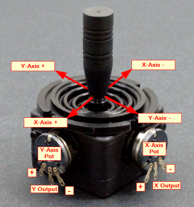
JH-D202X-R2_R4 Joystick 5K ‚œ Controls
Assigning which potentiometer is the X or Y is arbitrary and relative to the orientation of the joystick once it is mounted.
The labels in the picture just serve to provide on starting reference point.
When wiring the potentiometers, the center connection provides the output signal which represents the position of the joystick.
The two outside connections are typically hooked up to Vcc and ground to match the MCU. The + and ‚œ direction is relative to how the Vcc and grounds are connected to the potentiometers. These can be swapped if it is desired to swap the direction of the signal output as the joystick is moved.
OUR EVALUATION RESULTS:
These modules are quite useful for integrating into a final application such as for robotic control.
The program below illustrates and tests the basic functionality of the module. It reports the current state of the X-Axis and Y-Axis out to the Serial Monitor window.
The program uses analog pins A0 and A1, but these can be any 2 analog pins.
Write Your Own Review

Bestsellers

10/100/1000 5 Port Switch
ZAR 1,397.77
ZAR 1,215.45

SONOFF BASICR2- Wi-Fi Wireless Smart Switch
ZAR 156.96
ZAR 136.49
